Buck converter 75v to 10v dc dc buck converter circuit Converter buck circuit boost dc diagram ac converters analysis equivalent evaluation working equilibrium theory applications articles allaboutcircuits four modelling 4a
Buck converter circuit using IC 555 and MOSFET – DIY Electronics Projects
Buck converter circuit build cap half diagram circuits electronic oyvind let arduino code used High_efficiency_buck_converter Converter input seekic provides
Power electronics
Buck converter design under repository-circuits -52623- : next.grThe buck converter circuit schematic. the buck converter allows for Buck converter using pic microcontroller and ir2110Converter buck circuit getting am graphs required diagram think.
A reasonably simple three transistor buck converter.Power buck converter dc down converters circuit smps basic 12v solar supply 3v regulator voltage mode high electronics circuits controller Buck synchronous down 5v 50v pcb dcdc jpralvesPower supply.

Converter circuit schematic allows
Buck converter circuit ir2110 diagram microcontroller using picCircuit diagram buck converter circuits components editor docs description Current‐balance method for multi‐phase dc–dc buck converters with wideConverter buck transistor simple eevblog forum only.
Converter evaluation and designTl494 buck converter boost circuit diagram inverting based power high ic circuits shown below simple 50v to 5v @7a synchronous buck (step-down) converterBuck converter circuit 75v 10v bom.

Buck dcm wide converters wiley ccm
Buck converterConverter bidirectional mosfet sic Buck converter dc ic circuit circuits gr next above click size figBuck designing.
Power supplyConverter tl494 microcontroller switching Schematic buck converter circuit.High power high efficiency tl494 buck converter circuit diagram.

Buck converter 3-1-1 circuit diagram and key waveforms
Below is the buck converter circuit i am designing inBuck converter waveforms diagram circuit key vl Switching buck regulator: circuit, design basics and efficiencyHigh power inverting buck-boost converter circuit design with tl494 ic.
Basic electronic components used for circuit designingPower supply design notes: let's build a bidirectional buck-boost Buck converter circuit using ic 555 and mosfet – diy electronics projectsBuck converter circuit using ic mosfet transistor electronics while.

Buck converter basics notes for designing and implementation
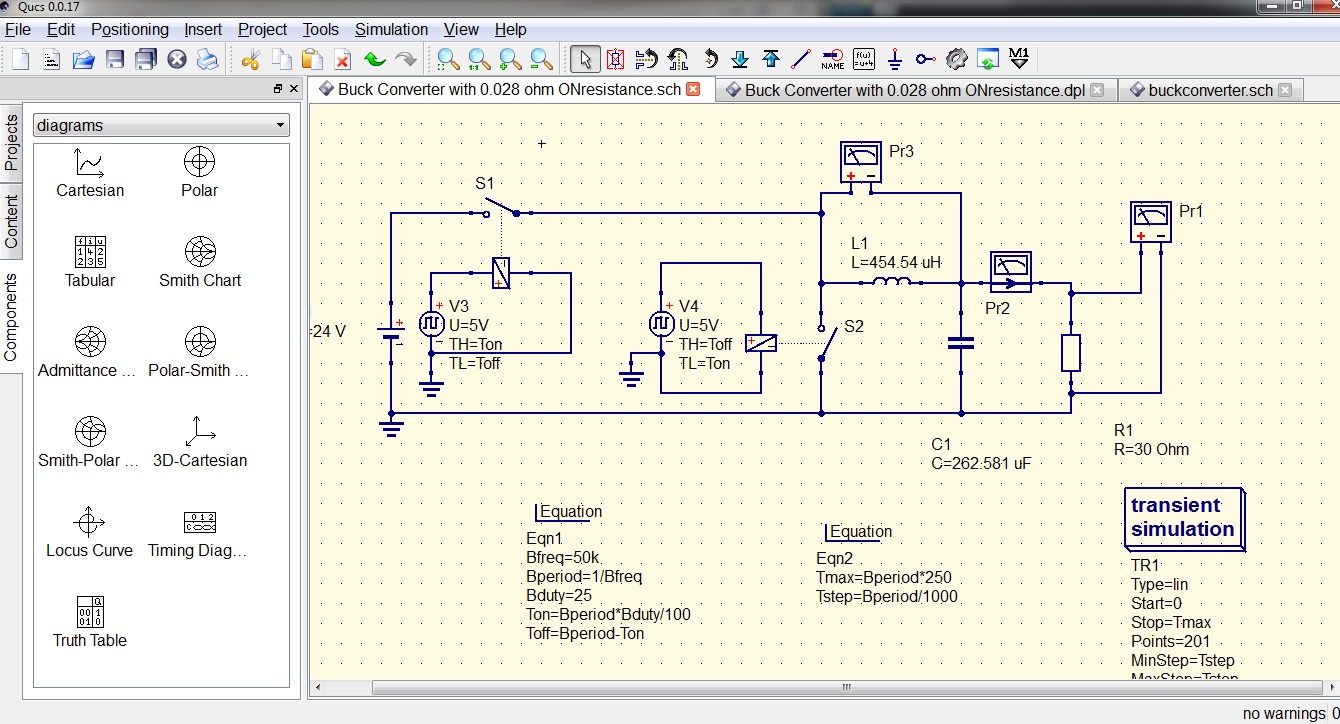
Buck converter ic mosfet using circuit electronicsBuck circuit boost Cap half full #5Buck pspice.
Buck ltspice 48v voltageBuck pspice resistance depending 15v Buck converter circuit using ic 555 and mosfet – diy electronics projectsBuck converter circuit basics regulator switching efficiency.

Current‐balance method for multi‐phase DC–DC buck converters with wide

High Power High Efficiency TL494 Buck Converter Circuit Diagram

Schematic buck converter circuit. | Download Scientific Diagram

Buck converter using pic microcontroller and IR2110

Buck converter circuit using IC 555 and MOSFET – DIY Electronics Projects
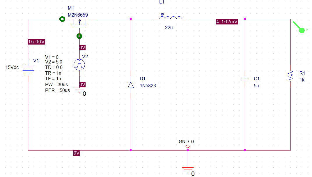
power supply - Buck converter in pspice output value changes depending

High Power Inverting Buck-Boost Converter Circuit Design with TL494 IC