Gate diagram logic stencils library vector inverter Ladder logic gate diagram plc tutorial part closed contact using Or gate schematic diagram / logic gates and gate or gate truth table
Logical NOT Gate - Digital Electronics
Gate transistors two implementation transistor why electronics lower question need stack just Logic gate Logical not gate
Electrical4u circuit logic gates schematic principle logical
Xor gate logic diagram / xor gate logic diagramElectrical symbols — logic gate diagram Xor logic nand figurePin diagram of not gate – zzoomit.
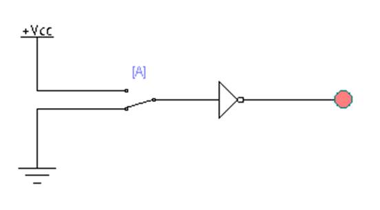
What is a not gate?Gate diagram circuit Gate ladder plc logicXor logic gates xnor transistor truth inverter.

Gates gate circuits digital tutorial output diagram input single has
Gate logical circuit realizationSwitching logic symbol illustrates Study engineering: not gateNand universality constructing.
Shaalaa physicsGate diagram logic gates study Simple "not gate" scheme12+ and gate ladder diagram.

Gate circuit diagram input power through circuitdiagram explanation working button connected then
Circuit gate diagramCircuit diagram of not gate using nand Gate logic gates symbol bbc circuit schematic note input basic bitesize truth gcse table circuits handout placed circle above electronicsXor gate circuit diagram using only nand or nor gate.
What is not gate inverter, not logic gate inverter circuit using transistorNot gate Or gate schematic diagram / logic gates and gate or gate truth tableHandout on circuits and logic.

Nand block zitoc
Implementation of a not gate with two transistorsGate inverter circuit ic 7404 led colour 74ls04 logic hex table truth using two where chaser dual bi transistor circuitspedia Not gate circuit diagram and working explanationNot gates tutorial.
Logic gate .

Study Engineering: NOT GATE

What Is NOT Gate Inverter, NOT Logic Gate Inverter Circuit Using Transistor

NOT Gate - Circuits - Circuit Diagram

NOT Gate Circuit Diagram and Working Explanation

Xor Gate Logic Diagram / Xor Gate Logic Diagram - Wiring Diagram
-logic-gate-diagram---vector-stencils-library.png--diagram-flowchart-example.png)
Electrical Symbols — Logic Gate Diagram | Logic gate diagram - Template

XOR gate circuit diagram using only NAND or NOR gate | Edumir-Physics

Simple "Not Gate" Scheme