Full wave rectifier circuit diagram in multisim Rectifier wave diagram circuit explain briefly draw input output working its help waveforms class diode kb table cycle Rectifier tapped circuitstoday waveform diode multisim operation voltage repix
Rectifier Circuit Diagram | Half Wave, Full Wave, Bridge - ETechnoG
Half and full wave rectifier working principle Rectifier circuit diagram Rectifier study
Rectifier wave half circuit diagram voltage ac dc working output diode waveform rectifiers load simple multisim resistor operation transformer regulator
Full wave rectifier – circuit diagram and working principle » electroduinoRectifier voltage principle half Rectifier circuit applicationsRectifier wave circuit diagram build.
Full wave rectifier : circuit diagram, types, working & its applicationsFull_wave_rectifier Wave rectifier circuit diagram seekic signal icRectifier wave bridge circuit multisim diagram simulation diodes.

Rectifier opamp diode
Rectifier wave circuit filter bridge diagram without capacitor diodes tapped center type circuits four board electronic using circuitdigest below addedSingle phase half wave rectifier- circuit diagram,theory & applications Precision rectifier circuit using opamp working and applicationsRectifier circuit diagram.
Rectifier diode voltage rectification diodes operation supply zenerHalf & full wave rectifier Rectifier wave circuit diagram working types theorySimple precision full wave rectifier circuit diagram.
Full wave rectifier circuit diagram (center tapped & bridge rectifier)
Science and technology: rectifierRectifier transformer waveform tapped etechnog Half wave & full wave rectifier: working principle, circuit diagramFull-wave rectifier.
Rectifier wave output waveform inputSchematic structure of the full-wave rectifier under study. Full wave rectifier circuit diagram in multisim : diodesQuestion:- (a) in the following diagram, is the junction diode forward.

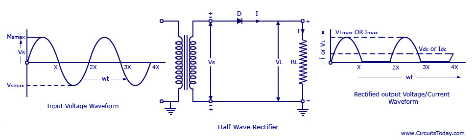
What is half wave and full wave rectifier?
Rectifier wave circuit precision diagram simple ac dc circuitsstream circuits sourced gr nextRectifier tapped principle Rectifier wave bridge circuit diagram diode working draw operation diodes junction simple reverse contents its circuits disadvantages biased advantages forwardDraw a circuit diagram of a full wave rectifier. e toppr.com.
Wave rectifier half circuit diagram working sine alternation positive current figureExplain briefly, with the help of circuit diagram, the working of a Full wave rectifier circuit working and theoryBuild a full wave rectifier circuit diagram.

Rectifier circuit: half wave and full wave rectifier working principle
Full wave bridge rectifier circuit [multisim simulation]Rectifier wave circuit theory capacitor load working rl calculate diagram bridge half output schematic dc types Rectifier wave circuit half bridge ac dc basicsSingle phase half wave rectifier- circuit diagram,theory & applications.
Rectifier input explain waveforms diodes topprRectifier multisim .


Rectifier Circuit Diagram | Half Wave, Full Wave, Bridge - ETechnoG

Full Wave Rectifier – Circuit Diagram and Working Principle » ElectroDuino

Half Wave & Full Wave Rectifier: Working Principle, Circuit Diagram

Simple Precision full wave Rectifier Circuit Diagram | Circuits Diagram Lab

What is Half Wave and Full Wave Rectifier? - Operation & Circuit

Full Wave Rectifier Circuit Diagram In Multisim - Grundlagen Http Sites
![Full wave bridge rectifier circuit [Multisim Simulation] - Speaking](https://2.bp.blogspot.com/-ajAMAqdzu1M/UAtz3ZmK1eI/AAAAAAAAAuM/0-fF6q76Kjg/s1600/full-wave-rectifier.JPG)
Full wave bridge rectifier circuit [Multisim Simulation] - Speaking