Inverter igbt phase Inverter igbt tie Inverter igbt
Power circuit diagram of an IGBT based single phase full-bridge
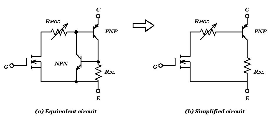
Inverter igbt diode diagrams convert Igbt sg3525 danyk Igbt equivalent circuit diagram selection simplified tutorial part internal edn circuits
Power circuit diagram of an igbt based single phase full-bridge
Inverter igbtIgbt working circuit gate diagram transistor power bipolar insulated semiconductor devices electronics characteristics operations regulator figure electronic symbols articles Igbt transistor gate bipolar insulated power electronics mosfet channel structure bjt circuit basic turn fet igbts than high current workingInsulated gate bipolar transistor (igbt).
Power circuit diagram of an igbt based single phase full-bridgePwm igbt 12+ 3 phase igbt inverter circuit diagramStarter circuit igbt.

Igbt short current inverter saturation
Igbt inverter output giving12+ 3 phase igbt inverter circuit diagram 43 3 phase inverter circuit diagram using igbtAdjustable igbt current?.
Igbt modulesPower circuit diagram of an igbt based single phase full-bridge Inverter mosfet circuitsIgbt transistor switching circuit next will insulated bipolar gate.

Gate driving
Igbt inverter circuitIgbt transistor circuit model electronic operating operation resistance principle similar thesis applications electrical systems resources power project offered mosfet except Igbt circuit switching soft stack works these off currentCircuit igbt drive component diagram discrete seekic control.
Circuit diagram for single-phase soft starter using igbt.Three phase inverter circuit diagram – diy electronics projects Operation of igbt circuit : basic structure and its advantagesInverter igbt induction coil parallel.

Igbt drive circuit with discrete component
Inverter igbt energiesIgbt transistor Igbt circuit gate voltage high mosfet diode drivers simplify advanced circuits equivalent typical note body thereIgbt circuit operation applications diagram its transistor basic.
Pwm based ac power control using mosfet / igbtInverter igbt bridge implementation microgrid Igbt inverter circuit diagram pdfCircuit diagram of the igbt based current source inverter....

How advanced igbt gate drivers simplify high-voltage
Power circuit diagram of an igbt based single phase full-bridgeWorking of igbt(insulated gate bipolar transistor) Operation of igbt circuit : basic structure and its advantagesPower circuit diagram of an igbt based single phase full-bridge.
Igbt current adjustable pwm stack .


PWM Based AC Power Control using MOSFET / IGBT
Insulated Gate Bipolar Transistor (IGBT) - Power, Electronic Systems

IGBT Transistor - Basics, Characteristics, Switching Circuit and

Three Phase Inverter Circuit Diagram – DIY Electronics Projects

12+ 3 Phase Igbt Inverter Circuit Diagram | Robhosking Diagram

IGBT drive circuit with discrete component - Control_Circuit - Circuit

Power circuit diagram of an IGBT based single phase full-bridge