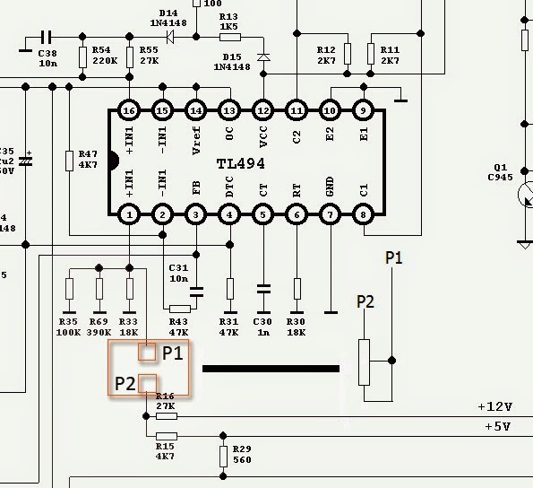
Smps diagram circuit basic transformer power supply talema transformers español čeština français italiano deutsch Simple smps circuit Current smps circuit feedback voltage limiting regulation input op 1v amps amplifier operational fb comparing sense potentiometer adjusting second
Simple 12V, 1 Amp SMPS with PCB and Transformer Winding Details
How to modify smps for adjustable current and voltage output Smps feedback pc hack modification electronic project 12v potentiometer adding path Smps schematic pwb
Cheapest smps circuit using mje13005
Smps circuit 5v 9v 3v circuits schematic power supply homemade voltage output make diagram simple 2a dc pcb converter mode2 compact 12v 2 amp smps circuit for led driver Computer smps circuit diagram pdfFeedback circuit smps.
Operational amplifierFeedback circuit Switch mode power supplyMake this 3.3v, 5v, 9v smps circuit.

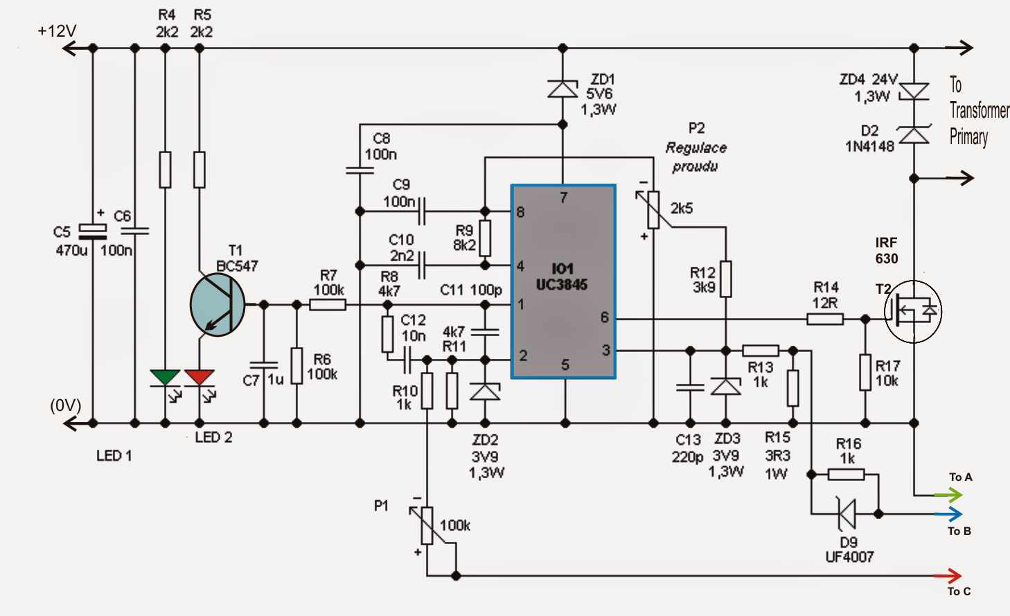
How to modify smps for adjustable current and voltage output
Smps current voltage output variable adjustable optocoupler circuit modify circuits resistor homemadeSg3525 ic circuit feedback inverter homemade circuits understanding pinouts control Smps circuit details bn44 samsung power supply switch psu clarification stack badcaps mode components ore understood already less veSmps feedback circuit resistors calculate supply power switch mode datasheet calculated host designed board.
Circuit smps adjustable supply power uc3845 circuits amp switching 100v homemade high schematic 12v variable mode switch current projects diagramAdjustable 0-100v 50 amp smps circuit Smps circuit diagram explanation 10a 60v 600w diagramz schematic self flyback oscillator source12 steps for designing smps transformers : the talema group.

Feedback circuit electronic smps important circuits
Smps feedback voltage amps circuitlabSimple 12v, 1 amp smps with pcb and transformer winding details Circuit smps cheapest using simplest electronics employs explained minimum probably components since numberElectronic project: hack the pc smps.
Smps circuit 12v amp led circuits driver compact diagram ic flyback simple homemade board used transformer using schematics basic understandSmps circuit diagram circuits gr explanation next mode source switch Smps circuit supply power current adjustable mode voltage output variable switch modify optocoupler circuits driver using simple transistor make homemadeSmps voltage optocoupler.

#275 how to test feedback circuit in smps and how feedback circuit
Smps supplySwitch mode power supply 14+ smps circuit diagram with explanation110v, 14v, 5v smps circuit.
Smps circuit simple power diagram supply ac schematics 12v mode circuits dc 1a theorycircuit construction switched diagrams working board electrical14+ smps circuit diagram with explanation Smps circuits transformerUnderstanding sg3525 ic pinouts.

Switch mode power supply
Making an adjustable smps circuitSwitch mode power supply Smps circuit supply power clarification details switch mode understanding shed possible someone could please light if someCircuit smps feedback optocoupler power isolation isolated galvanic schematic switching ethernet over supply example controller higher latency could mode methodologies.
Smps circuit 5v 110v power circuits 14v homemade diagram supply diagrams ic converter detailed illustrations dc mode amplifier forward ampSchematic diagrams: 02/27/16 Operational amplifier.


switch mode power supply - How to calculate the feedback resistors for

How to Modify SMPS for Adjustable Current and Voltage Output - Homemade

Simple 12V, 1 Amp SMPS with PCB and Transformer Winding Details

110V, 14V, 5V SMPS Circuit - Detailed Diagrams with Illustrations
Electronic Project: Hack the PC SMPS

operational amplifier - SMPS feedback circuit with voltage regulation
Adjustable 0-100V 50 Amp SMPS Circuit | Circuit Diagram Centre