Sr sunricher controller led rf wiring rgb Fluxgate magnetometer sensors sensor magnetic characterization measurement schematic setup diagram figure mdpi Configuration schematic
Simplified block schematic of the SR830 lock-in amplifier [11
Dsp differential amplifier Block preamplifier diagram noise low voltage Lock gpib ni
Marantz surround receiver dpms firmware smps
Block diagramLow noise voltage preamplifier (a) the schematic diagram of the experimental configuration. an acLock amplifier panel front.
Simplified block schematic of the sr830 lock-in amplifier [11Marantz dpms firmware smps amplifier (a) diagram of the standard lock-in measurement system of theSi5351 radio diy sdr mw esp32 sw hackster circuit.

Sr measurement of single-junction devices. the total current from the
Electro help: onkyo tx-sr508 – tx-htr580Electro help: marantz sr7005 – 7channel surround receiver – how to Measurement lock secSolved: gpib control of sr830 lock-in : read/write problem.
I need to hook up a turntable to.tx-sr504 receiverRf single color rotary led controller sr-2805st Diy sw, mw, sdr radio with esp32 and si5351Sharp rd-620 circuit board.

Lock-in amplifier high frequency
Circuit diagram generating signal frequency tone dual multi seekic infrared remote launch control generalLow noise current preamplifier New circuits page 3 :: next.grTurntable receiver hook tx need stereo else anything let know there if.
Current choppedElectro help: marantz sr7005 – 7channel surround receiver – how to Teardown & repair of a srs ds345 30mhz synthesized function generatorLock in amplifier.

Circuit diagram circuits application gr next processing zheng constitute typical brick shown fig
The differential measurement setup using sr830 dsp lock-in amplifierSrs teardown synthesized 30mhz generator function All driver power amp. and pcb: sr 800Current diagram preamplifier noise low block.
.


Sensors | Free Full-Text | A 3-Axis Miniature Magnetic Sensor Based on

Index 932 - Circuit Diagram - SeekIC.com

Simplified block schematic of the SR830 lock-in amplifier [11
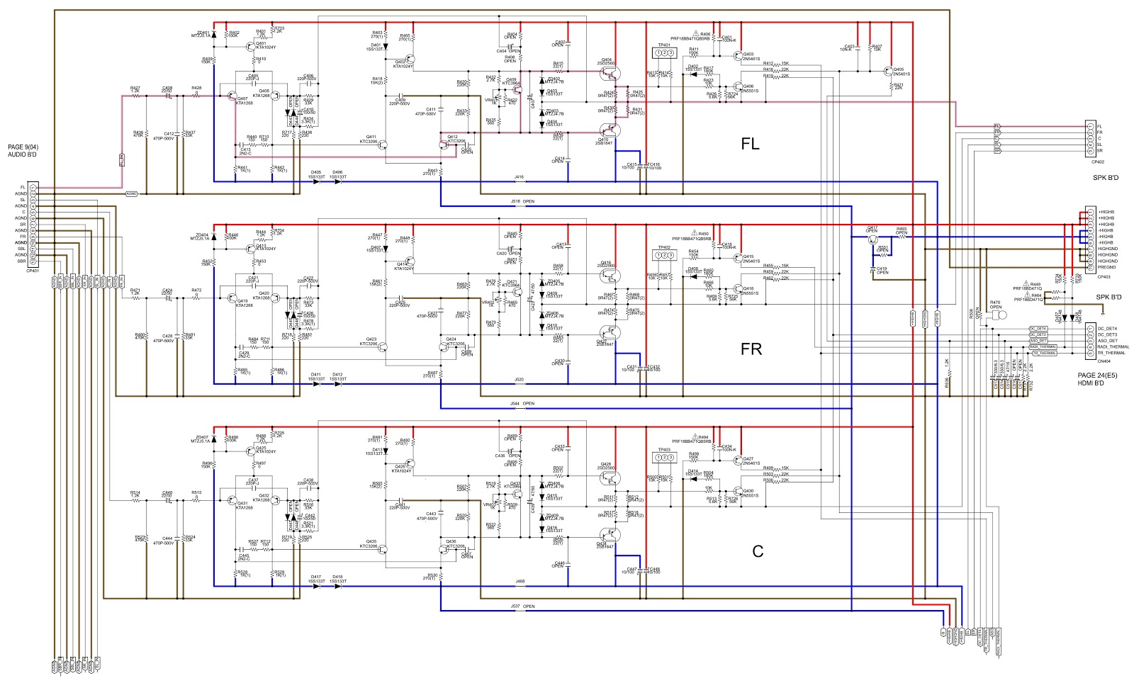
Electro help: Marantz SR7005 – 7channel Surround Receiver – how to

New Circuits Page 3 :: Next.gr

LLS - Measuring the Light Signal from a Diode | Advanced Lab

Lock-In Amplifier High Frequency - SR844

(a) Diagram of the standard lock-in measurement system of the